The International Archives of the Photogrammetry, Remote Sensing and Spatial Information Sciences, Volume XLII-5/W2, 2019
Measurement, Visualisation and Processing in BIM for Design and Construction Management, 24–25 September 2019, Prague, Czech Republic
BUILDING INFORMATION MODELING APPLIED TO THE INDUSTRIAL ARCHITECTURAL MONUMENTS CASE STUDY OF SAINT PETERSBURG
E.S. Soonwald 1, A.E. Wojnarowski 1,2, S.G. Tikhonov 1, O.V.Artemeva 2, S.V. Tyurin 2
1 PHOTOGRAMMETRIA Research and Production Enterprise, St. Petersburg, Russia - info@photogrammetria.ru
2 Saint Petersburg State University, Department of Cartography and Geoinformatics, St. Petersburg, Russia - a.vojnarovsky@spbu.ru, o.artemieva@spbu.ru, s.tjurin@spbu.ru
ABSTRACT:
Development and implementation of information models of spatial objects affect broadest application areas currently. Building Information Models (BIMs) are now becoming extremely popular. These models are able to describe a great number characteristics of building or engineering construction, including physical and functional properties, economic parameters, visual parameters, etc. BIM use is introduced currently as the mandatory aspect of building life cycle management, from design and construction to demolition. However, implementation of the BIM concept into the reconstruction, restoration and conservation of historical and cultural heritage remains the least developed domain. Therefore, research and development activities concerned with HBIMs (Historical Building Information Models) are particularly relevant. Saint Petersburg being the second largest Russian city has a huge number of architectural monuments, while industrial architecture composes a special category of these monuments. We provided a number of research and development activities devoted to the 3D information modelling of industrial architectural monuments located in St. Petersburg. Context of these works was established by the reconstruction and adaptation of these monuments to modern needs. 3D models of buildings were produced basing on results of the laser scanning and photogrammetric survey. Basing on our work, we have formalized main approaches to design and implementation of Building Information Models of the industrial architectural monuments.
1. INTRODUCTION
The advanced approaches to spatially distributed objects imply development and use of their information models. A model of a country, region, city, a particular building is based on advanced computer technologies. Every object (a physical object or a phenomenon) integrated into the model has specific characteristics (attributes) attached to it through a database. Connection of databases with the object coordinates and their attributes enables the specialists to evaluate the condition of objects and to ensure effective managerial decisions on them.
Nowadays, this approach is implemented actively into the construction industry. Building information modeling (BIM) is a tool that helps to manage a facility throughout the whole lifecycle: from the design stage and construction to demolition. A digital building integrated into the information model exists in whole and integrated form: a change of a particular parameter leads to a change of the whole construction. Such connection is possible exactly through the parametric relationships between the object parts and object attributes recorded in the databases. This allows to design, construct and track the lifecycle of the building basing on its digital representation with higher quality of analysis than it is achievable without BIM.
As a modeling concept, BIM was proposed and introduced in 1970s (Eastman et al., 1974; Ruffle, 1986). Modern meaning of this term was introduced first time in the middle of 1980s. (Nederveen et al., 1992). The use of BIM concept has become traditional at design, construction and maintenance stages throughout a building lifecycle. Since 2016, the Russian Federation has developed a roadmap for implementation of the information modeling technology into construction domain. (The list of instructions following a meeting of the State Council May 17, 2016)
Basic principles of BIM development:
1. Use of 3D space measurements and design of 3D models
2. Storage of all attributive and design documentation in a database connected to certain building elements
3. Interconnection of all object parameters (intellectual parametrization)
4. Maximum automation (generation of all schemes and drawings upon user’s request considering the given model parameters)
5. Intellectual and financial construction and object support calculations (cost reduction)
Specific features of BIM as a parametric model:
1. Online mode of parameters’ change: if a particular parameter changes, the whole model changes
2. Possibility to information obtaining from any part of the project, including geometry, dimensions, technical characteristics and other data particles
3. Ongoing scaling: changes can be introduced into certain elements, after the elements are restored, the introduced changes will automatically affect the related areas
4. Decomposition possibility, the information model allows to view any object in detail, it is possible to retrieve the drawing (of the window opening, floor beams, downpipe, etc.) that can be executed in 2D or 3D format (BIM, 2019).
Owing to the principles of the BIM development and to the relevant software that implements the BIM concept, nowadays the information modeling has been used widely at design and construction stage of new buildings. The use of information technology has a great technological and financial impact at every stage of work. The development of BIM itself is becoming an important part of the process and doesn’t require any additional material expenditures. In fact, a new building is erected from scratch and everything that is put into the project (physical dimensions, materials, operational characteristics, etc.) immediately becomes an element of its information model as a part of such new project, and could be further revised and
detailed at construction stage.
The whole complex of tasks for development and use of information models relating to historic buildings and landmarked buildings has significant differences. These differences are so material that there is even a special term invented for the information models of such types of objects,
namely HBIM (Historic Building Information Model).
Here are several key differences:
1. Information model is created for an existing building, rather than for the one that is being erected from scratch
2. In order to provide precise physical measurements of the future model, a detailed 3D survey of a building is required. In general, the 3D laser scanning and photogrammetry methods are used currently for these tasks
3. It is necessary to collect and analyze all historical literature related to the building, all available architectural and construction documentation
4. It is necessary to carry out field architectural and archeological, chemical, engineering and other surveys to fund out and determine more precisely the details which were not available in the reference materials, and to obtain the missing information about the building
5. An information model of a historic building poses additional challenges such as technical and organizational issues related to substandard parameters of the building (curved walls, complicated shapes, presence of architectural details, non-standard materials, etc.)
Another essential point is that the theory and methodology of development and use of BIM for historic buildings is fairly new as compared to the history of use of BIM technology for new construction. The first publications dedicated to the issues of HBIM were published merely 10 years ago (Murphy et al. 2009, 2012; Fai et al., 2011; Saygi et al., 2013; Brumana et al., 2013; Logothetis et al., 2015; Oreni et al.; 2014; etc.) Today, the concept of HBIM is at the development stage as opposed to nearly classic BIM concept. The use of information modeling at design stage of restoration of landmarked buildings, or restoration and adaptation of old buildings for new use, can improve significantly the quality of such work and can not only provide technical and financial impact but also contribute significantly to the task of preservation of cultural heritage. In fact, the first four points out of five ones listed above HBIM characterizing specifics are determined by the specifics of restoration of old buildings, and are implemented regardless of a particular design technology employed (information model-based or a classic model). Thus, the use of BIM technology for restoration of old buildings is essentially a new type of workflow management which doesn’t change the meaning thereof. Undoubtedly, the effective use of information modeling systems in restoration requires serious adaptation, which would consider both the specifics of physical dimensions and construction of old historic buildings, and the specifics of restoration work processes.
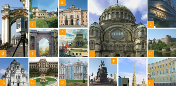
Our team has developed information models for several landmarked buildings of Saint Petersburg (Russia). It is a well-known fact that despite its young age, Saint Petersburg boasts a number of architectural masterpieces, which were mainly built when Saint Petersburg was the capital of the Russian Empire (from the beginning of the 18th till the beginning of the 20th century). Unlike most European cities, Saint Petersburg was founded and developed as a capital and was based on the integral urban development plan. The historic center, historic industrial belt that encircles the historic center, and the new outer-lying residential districts are clearly distinguished in the urban area. We created information models for objects which refer to industrial (or so called grey) belt of the city (Figure 1).
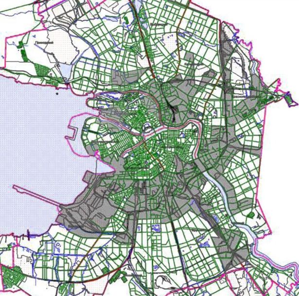
Figure 1. The grey belt of Saint Petersburg – historic districts of industrial development
As it can be seen in Figure 1, the areas of industrial development are significantly greater than the area of historic center, which is a UNESCO world heritage site. Therewith, the blocks of grey belt include many landmarks of industrial architecture of Saint Petersburg and reflect all periods of national industrial history: pre-industrial period (18th century), initial industrialization (the first half of the 19th century), late industrialization (the second half of the 19th century – beginning of the 20th century), and Soviet industrialization (1917-1930s), while each period has its own specific characteristics. (Stieglitz, 2002). Nowadays, many production sites located within this territory either get closed or moved outside the city center, and the grey belt of Saint Petersburg is becoming increasingly attractive for investors as a renovation area. Industrial buildings are getting modernized and adapted for new purposes. Nevertheless, it is also important to preserve the external character of these buildings in both historic and financial terms, since the value of these buildings is composed by the fact that they constitute a part of the common historic complex, which in its turn presents a significant part of the historic city area. Furthermore, as was already mentioned, many buildings located within the grey belt area are world heritage sites, the landmarks of the industrial architecture and are protected by the government. Thus, these buildings come within the provisions of rules for repair and restoration works. On the other hand, owing to a relative simplicity of construction and concise execution, the industrial architecture buildings are quite convenient objects for use and testing of new technology of information modeling both at the design stage, as well as at renovation and construction stages.
Furthermore, the article evaluates an example of development of an information model for a cultural heritage site Metalworker’s Shop of Saint Petersburg Partnership of Rail Car Manufacturing Plant of the Prodvagon Association of Rail Car Manufacturing Plants located at 115B Moskovsky Ave., Saint Petersburg (Figure 2).
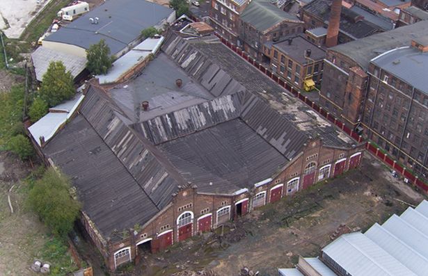
Figure 2. Aerial view of Metalworker’s Shop
2. METHODS
2.1. Historic Reference.
The building of the workshop was constructed in 1914 as per the design of engineer Grigoriy Rozovskiy; in 1931 a two-storey annex was added to the north facade. The building is a historical and architectural landmark of a regional status and a specimen of industrial architecture in a late industrial modernism and constructivism style with rare constructive structural design concept intended for industrial purposes. It is a brick building with 7,000 sq. m. area and nearly 104,000 cub. m. space. It is composed of the two parts: one-storey shop and a two-storey annex with back and service rooms. It has a strict facade design with big gateways at the front and curved mouldings, small windows with archivolts above and gables. The window openings of the side facades are designed with archivolts with capstones and mouldings. Both window openings and gateways are within the pillars between rectilinear strips accompanied by denticles under the upper bead. The strips of front facades are finished with caps overhanging the parapet wall. A complicated metal structure is dominant in the spacious internal design; it includes 73 riveted stanchions and a complex system of laced steel trusses and timber beams, lanterns. Due to the annex on the north facade, historic openings in the wall were laid and new ones were made, several design elements got lost. Annex showcases a hallway system with small rooms separated by partition walls, 3 internal staircases, single-pitched roof on I-beams, facades without decorative fixtures, window and door openings of various sizes and fillings. The building has preserved its original appearance and is listed as a cultural heritage site.
2.2. Development of a HBIM of Metalworker’s Shop.
The main objective of the project is to develop a HBIM as of the moment of survey and to capture the intrinsic unevenness, deformations, fractures, equipment remains. Not only structural parts, but also the remains of industrial equipment such as air ducts, pipes, railings, ambries left after the disassembly of equipment, process cellars were subject to modeling. First, the building was cleared of rubbish, most of equipment and utility systems. The degree of model detailing is 5 cm.
The objective is to use the model as a basis for development of a project of contemporary business center, which assumes the preservation of the original appearance and building structure.
The model was elaborated basing on laser scanning data with the use of FARO Focus 3D laser scanning system. Two hundred (202) scans were obtained during the survey (162 inside the building and 40 outside) which were composed in ScanIMAGER software using unified object coordinate system and municipal system of heights. Furthermore, the data was converted into *.rcs format in Autodesk ReCap and uploaded to Autodesk Revit (Figure 3).
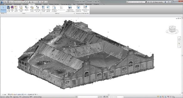
Figure 3. Point 3D model of building in Revit project
Due to its high spatial resolution, the point model of object serves as a graphic and informative basis for BIM elaboration. Top-down approach was used for modeling in Autodesk Revit: point model analysis, identification of semantic and geometric features of the building, classification and selection of modeling method for a 3D model generation.
Practically, three 3D modeling options were used:
1. Selection of object from the system library that would correspond in terms of meaning and size and its integration into the model; An example of system objects could be walls, slabs, metal structure parts (angle elements, C-profiles, I-beams); Notably, the metal structure parts were used both directly as roof beams and as part of frame system (roof truss, stanchion)
2. Development of new objects with variable parameters for repeated elements and parts of bearing constructions; For example, window openings with architectural casing on side facades, stanchions, roof trusses (Figure 4); This method is justified when it’s possible to set a small (finite) number of object parameters, the element is frequently presented, and has high significance (it’s planned to be accounted analysis and computations)
3. Development of context objects with the use of Component > Model In-place command; This command allows to create objects of nearly any shape, therefore it’s recommended to use this method of object development for non-standard repeated elements, which are not used as the building frame
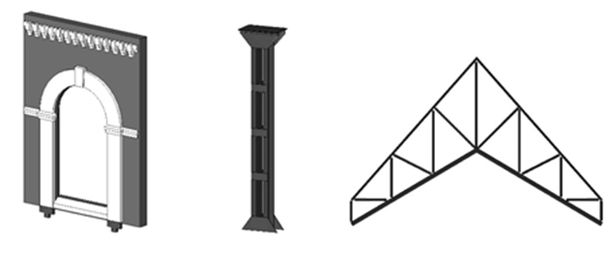
Figure 4. Left to right: window opening, stanchion, roof truss
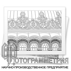
During the model development, the priority was given to objects from the system library and to the newly created objects. All elements of bearing construction were modelled in this way. However, oftentimes the context object development feature was used. This is due to a great variety of object types. At least 18 types of decorative fixtures were outlined on facades, meanwhile the elements of one type could be much different from the other in terms of size and finishing (Figure 5). The context objects were also used to replace the equipment, niches and holes that were present in the building after disassembly. Finally, it makes more sense to model the unique distinct objects based on the existing ones.
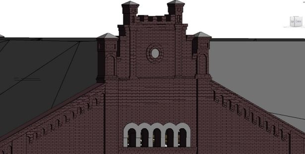
Figure 5. Section of front facade with decorative fixtures
During the modeling, special attention was paid to the elements of bearing construction (walls, stanchions, roof trusses) of the main building. Walls are the basis of the model. They set the building configuration and are used to outline the floor structure, to insert the window and door openings. The building had brick walls with a thickness of three bricks, or 720 mm. The outline of gables on the front facade was made with the use of Edit a Profile function. The walls of the annex had a variable thickness, therefore they were made of several walls built one on another or one next to another. Local topography was considered during the modeling of floor structure, as well as earthfill, and bases, or insets of the disassembled equipment. The floor structure configuration was done with the use of typical shape-change points with assignment of corresponding heights. Earthfill and bases were modelled as context objects. Stanchions were copied following their actual position taking into account rotations, displacements and inclinations (Figure 6).
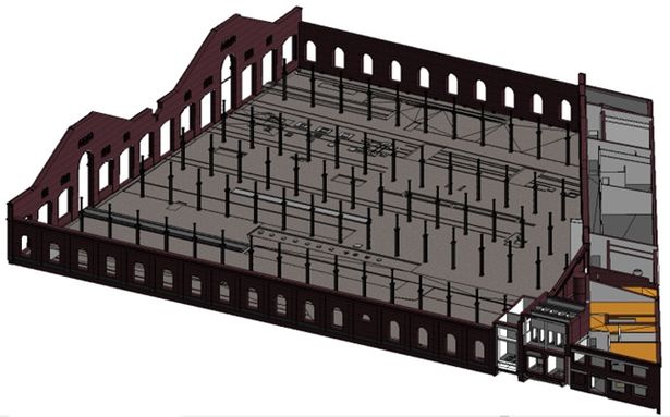
Figure 6. Intermediate model with walls, floor structure and stanchions
The most time-consuming part of modeling was the development of laced system of trusses and beams especially at the stage of data scanning. Six types of trusses intertwisted into an intricate pattern below the roof at the height of 8 to 16 meters (Figure 7). The total number of trusses is 172 and each one of them was to be positioned manually with allowance for its height, inclination and rotation.
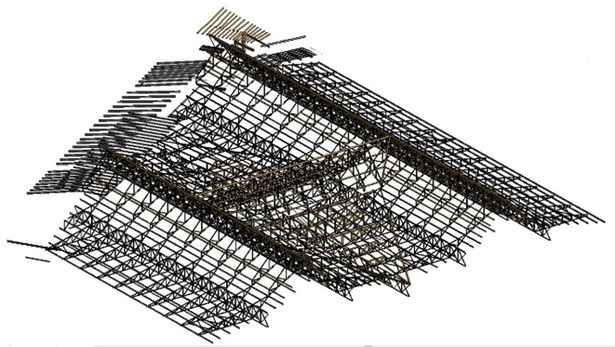
Figure 7. System of trusses and beams
At the final stage of modeling, the roof and ground surface along the facades were developed. The roof was modeled fragmentarily reflecting the thickness and topography, corresponding to the scanned data. The principle of roof modeling is similar to modeling of floor structure: the typical shape-change points with their heights were added. The ground level along the facades was modeled automatically with the use of Toposurface function: a typical topography points with coordinates and heights was captured from scanned data; then the data was exported as .txt files and uploaded to software as a basis for topography modeling. The resulting model is shown in Figure 8.
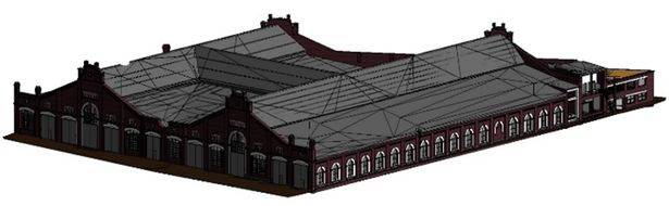
Figure 8. Final model of Metalworker’s Shop
As a result of development of a HBIM using Revit, a full set of drawings was obtained. The drawings were exported into AutoCAD, edited and finalized as per the technical specifications.
The key problem have to be resolved when developing a BIM of historic buildings is their faultiness. The key issues that were to be resolved manually: uneven walls, window and door openings different in terms of size, irregular grid of stanchions (different pitch), different distances between trusses, truss and stanchion rotation relative to each other (or to axis), different height, inconsistency of decorative fixtures. The causes of these issues could be different: from incompliance with the project at construction stage to temporary deformations, or to losses. As a result, the modeling process required more manual work than automated; the model had to be simplified, summarized and homogenized.
3. CONCLUSIONS
1. Nowadays, BIM is used actively at different stages of building lifecycle: design, construction and maintenance
2. The BIM technology is mostly suitable for new construction projects, where its use provides a significant technological and financial impact at every stage of design and construction
3. The application of BIM technology for renovation of old buildings and restoration of landmarked buildings is currently undeveloped; This area of information modeling requires additional research and development to cover various ranges of problems: from development of new software or adaptation of existing one for HBIM purposes to restoration process organization basing on the use of information technologies
4. Our team has developed information models for several industrial landmarked buildings of Saint Petersburg (Russia) for the purposes of restoration and adaptation for current needs; The approach and methods used for development of BIM were exemplified by development of the information model for a cultural heritage site Metalworker’s Shop of Saint Petersburg Partnership of Rail Car Manufacturing Plant of a Prodvagon Association of Rail Car Manufacturing Plants located at 115B Moskovsky Ave.
5. Precise measurements of the facility were obtained as a result of the 3D laser scanning and partially of the photogrammetric survey
6. The development of an information model was carried out basing on the point cloud of Autodesk Revit software. All major structural points of the building were modelled as well as the remains of industrial equipment
7. Three options of 3D modeling were mostly used: a) selection of objects from system library; b) development of new objects with variable parameters; c) development of context objects
8. The key problem of development of a BIM for historic buildings is their faultiness (uneven walls, different size and orientation of similar elements, etc.); This leads to additional manual work but ultimately it should be automated in the systems adapted for HBIM
REFERENCES
Autodesk, 2019. Architectural Design Technology, https://www.autodesk.ru/solutions/bim/architecture (15 May 2019)
BIM, 2019. Basic Principles of BIM design, http://bimforum.tilda.ws/osnovnie_principy_bim (20 February 2019)
Brumana, R., Oreni, D., Raimondi, A., Georgopoulos, A., Bregianni, A., 2013. From Survey to HBIM for Documentation, Dissemination and Management of Built Heritage. Digital Heritage International Congress (Digital Heritage), Oct. 28 – Nov. 1 2013, Marseille, pp. 497-504.
Eastman, C., Fisher, D., Lafue, G., Lividini, J., Stoker, D., Yessios, C., 1974. An Outline of the Building Description System. Institute of Physical Planning Research Report No. 50, Carnegie-Mellon University, 23 p.
Fai, S., Graham, K., Duckworth, T., Wood, N., Attar, R., 2011. Building Information Modeling and Heritage Documentation. Proceedings of the 23rd International Symposium, International Scientific Committee for Documentation of Cultural Heritage (CIPA), Prague, pp. 12-16.
Logothetis, S., Delinasiou, A., Stylianidis, E., 2015. Building Information Modelling for Cultural Heritage: a Review. ISPRS Ann. Photogramm., Remote. Sens. Spat. Inf. Sci., Vol. II-5/W3, pp. 177-183. doi:10.5194/isprsannals-II-5-W3-177-2015
Murphy, M., McGovern, E., 2009. Historic Building Information Modelling (HBIM). Structural Survey, Vol. 27, Issue 4, pp. 311-327.
Murphy, M., Dore, C., 2012. Integration of Historic Building Information Modelling (HBIM) and 3D GIS for Recording and Managing Cultural Heritage Sites. 18th International Conference on Virtual Systems and Multimedia (VSMM): Virtual Systems in the Information Society, 2-5 September 2012, Milan, Italy, pp. 369-376.
Nederveen, G., Tolman, F., 1992. Modelling Multiple Views on Buildings. Automation in Construction, 1(3), pp. 215- 24. doi:10.1016/0926-5805(92)90014-B.
Oreni, D., Brumana, R., Della Torre, S., Banfi, F., Barazzetti, L., Previtali, M., 2014. Survey Turned into HBIM: the Restoration and the Work Involved Concerning the Basilica di Collemaggio after the Earthquake (L'Aquila). ISPRS Ann. Photogramm., Remote. Sens. Spat. Inf. Sci. Vol. 2(5), pp. 267- 273.
Ruffle, S., 1986. Architectural Design Exposed: from Computer-aided-drawing to Computer-aided-design. Environments and Planning B: Planning and Design, pp. 385-389.
Saygi, G., Remondino, F., 2013. Management of Architectural Heritage Information in BIM and GIS: State-of-the-art and Future Perspectives. Int. Journal of Heritage in the Digital Era, Vol. 2(4), pp. 695-714. doi:10.1260/2047- 4970.2.4.695
Stieglitz, M., 2002. Industrial Architecture of St. Petersburg XVIII – First Half of the 20th Century: Historical and Cultural Problems. Doctoral dissertation, St. Petersburg, Russia, 458 p.
The List of Instructions Following a Meeting of the State Council 17 May 2016, http://kremlin.ru/acts/assignments/orders/52154b (20 September 2017)
Revised June 2019
#BIM #industrial_architectural_monuments #restoration #SaintPetersburg #BIMmodel #BuildingInformationModels


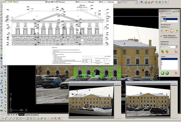

 Программный комплекс ScanIMAGER предназначен для обработки результатов трехмерного лазерного сканирования применительно к архитектурным обмерам. Он построен по модульному принципу и поставляется в различных модификациях.